-
Why the Right Tools Matter When the Clock Is Running
-
The 6-Step Pre-Replacement Checklist
-
Step 1: Rule Out a Power Supply Problem First
-
Step 2: Get Straight on Insulation Tester vs Megger Before You Need It
-
Step 3: Isolate the Sensor Circuit and Test Insulation Properly
-
Step 4: Check the Signal Loop and Terminations (Not Just the Sensor)
-
Step 5: Inspect the Process Connection Before You Blame the Instrument
-
Step 6: Test the Sensor in Isolation Against a Known Reference
-
Step 1: Rule Out a Power Supply Problem First
-
Common Mistakes to Avoid
Here's the thing nobody tells you about maintaining level instruments: most 'failed' level transmitters and tuning fork level sensors aren't failed at all. They're victims of bad wiring, bad power, or bad assumptions.
I learned this the expensive way. In my first year doing instrumentation maintenance (2017), I replaced a level transmitter that was working perfectly fine. The real issue? A loose ground connection on the cable tray. That $1,400 mistake plus a second night-shift visit taught me a lesson I've built into a checklist.
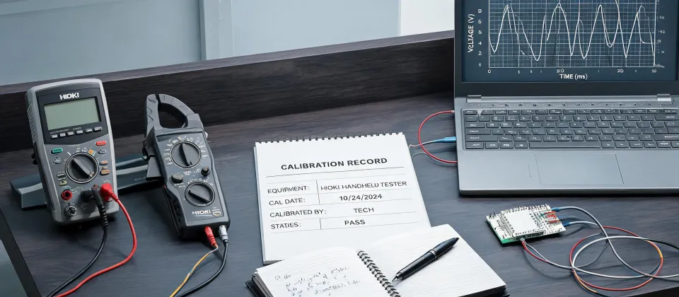
This checklist is for anyone who's staring at an erratic level transmitter or a tripping tuning fork level sensor and feeling pressure to fix it now. It's six steps, takes about 45 minutes, and it uses two tools I won't do field work without: a HIOKI insulation tester IR4056 and a HIOKI power quality analyzer.
Why the Right Tools Matter When the Clock Is Running
When a tank level reading goes wild and production is waiting, the natural instinct is to swap the sensor. I get it. But here's the counterintuitive truth: the 45 minutes you spend diagnosing will almost always cost less than the alternative.
Let's do the math I've used on our team. A replacement tuning fork level sensor is $400–$900 depending on the make (as of early 2025). A level transmitter is often well over $1,000. Add a rush-shipping fee in a deadline situation, and you're easily at $1,500 before the technician even climbs the ladder. The diagnosis, by comparison, is free if you own the tools, or a couple of hours of labor if you don't.
The question isn't whether you can afford to check. It's whether you can afford to not check.
Before we get into the steps, here's what you'll need on hand: a HIOKI IR4056 or equivalent insulation tester, a HIOKI power quality analyzer, a digital multimeter, a clean rag for the process connection inspection, and a HART communicator if your transmitters support it. If you're buying the IR4056, read the spec sheet before you buy—the five test voltages and the live-line warning are the features that matter in the field.
The 6-Step Pre-Replacement Checklist
Step 1: Rule Out a Power Supply Problem First
This is the step people skip because it's 'too basic.' Don't skip it.
I've said this before and I'll say it again: a level transmitter gets its power from somewhere, and if that somewhere is unstable, the transmitter will act exactly like it's dying. Dips, sags, frequency drift. All of them produce symptoms that look like a sensor failure.
Connect your HIOKI power quality analyzer to the supply feeding the instrument. Don't just measure the voltage once and walk away. Let it log for at least 15–30 minutes while the sensor is misbehaving. The HIOKI power quality analyzer's capture feature will catch transients that a digital multimeter simply cannot show you.
If you see voltage sags below the instrument's rated operating range, you've found your problem. The sensor isn't broken. The supply is.
Why does this matter? Because I've personally wasted an afternoon replacing a level transmitter that was only doing its job reflecting a voltage-starved power supply.
Step 2: Get Straight on Insulation Tester vs Megger Before You Need It
'Megger' is one of those brand names that became a generic term, like Kleenex. Technically, Megger is a company that makes insulation resistance testers. What people usually mean when they say 'give it a megger test' is: apply a high DC voltage and measure insulation resistance.
The HIOKI insulation tester IR4056 does exactly that, with five test voltages (50/100/250/500/1000 V) per HIOKI's published specifications. Here's the important part: you do not need the old mechanical crank-handled unit. Modern insulation testers like the IR4056 are battery powered, compact, and—critically—check for live voltage before applying the test voltage. That's a safety feature worth respecting.
The common misconception in the insulation tester vs megger comparison is that a multimeter's ohms range can replace an insulation test. It can't. A multimeter measures resistance at a low voltage—usually under 1 V. An insulation test at 500 V or 1000 V will reveal degraded insulation that looks perfectly fine to a multimeter. I assumed a $40 multimeter was good enough for insulation checks in my early days. That assumption cost me a near-miss incident and a $900 sensor that wasn't faulty. Learn from me on this one.
Step 3: Isolate the Sensor Circuit and Test Insulation Properly
Before you test any cable insulation, disconnect the sensor and the transmitter/PLC side. This isn't optional. If you test through the PLC input card, you'll read the card's components, not your cable's insulation.
With the circuit isolated, use the HIOKI IR4056 to test:
- Each conductor to ground (earth).
- Conductor-to-conductor, especially if it's a twisted pair.
- Conductor to shield, if the cable has one.
What should the readings look like? For a low-voltage control cable feeding a level transmitter or tuning fork level sensor, anything above 10 MΩ is generally acceptable. Below 1 MΩ is a red flag. Anywhere in between? Investigate further—check for moisture in the junction box, chafed jackets, or water ingress in the conduit.
One thing to watch: when you press the test button on the IR4056, it applies the test voltage for as long as you hold it. On a slightly damp cable, you'll often see the reading climb as the test current dries the insulation a little. That's why I always hold the test for at least 10 seconds, not just until the reading stops moving.
Step 4: Check the Signal Loop and Terminations (Not Just the Sensor)
A level transmitter typically outputs a 4–20 mA signal. A tuning fork level sensor usually has a switching output. Both depend on the integrity of the full loop, and both fail when a termination is loose or corroded.
Pull the terminations apart and physically inspect them. That sounds obvious, but I can't tell you how many 'intermittent level transmitter' faults I've traced back to a screw terminal that was barely holding one strand of wire.
Also check the receiving side. A common gotcha: the PLC analog input card is faulty, not the transmitter. I once spent two days troubleshooting a level transmitter that was perfectly healthy, only to find a blown fuse on the isolator feeding the PLC input. The tuning fork level sensor had nothing to do with it.
Isolate the sensor and measure its output directly. For a 4–20 mA loop, measure the loop current and compare it against the expected value for the known level. If the sensor responds to a known level change and produces a linear output, your sensor is almost certainly fine.
Step 5: Inspect the Process Connection Before You Blame the Instrument
This is the one people hate to hear, because it involves climbing up to the actual vessel.
For a tuning fork level sensor, look at the fork itself. Is there buildup? Coating? If the fork is covered with material, it may not oscillate correctly, causing false triggering. Cleaning the fork has saved me from replacing tuning fork level sensors that were never broken in the first place.
For a level transmitter, check the process flange, diaphragm, and impulse lines. A plugged impulse line makes a transmitter read wrongly—often a slow, drifting reading that mimics a dying sensor. A root valve left closed after a calibration does the same thing. The January 2024 incident at our plant changed how I think about this: the 'failed' level transmitter was sitting on a bench, tested perfect, while the real culprit was a technician who'd left the root valve shut. Don't let that be you.
Step 6: Test the Sensor in Isolation Against a Known Reference
If steps 1 through 5 all check out clean, now—and only now—do you test the sensor itself in isolation.
For a tuning fork level sensor, you can power the unit from a bench supply, apply material to the fork, and verify the switching output changes. For a level transmitter, use a HART communicator or a resistance substitution box to simulate the input and compare the output. Many modern level transmitters have a simulation mode that lets you verify the electronics without any process connection.
Document the results. (Note to self: I really should have been better about logging baseline readings years ago. A digital record of what 'normal' looks like makes every future diagnosis faster.)
Common Mistakes to Avoid
Over the years, I've made—or watched teammates make—the same mistakes again and again. Here are the ones I'd highlight:
- Testing insulation without disconnecting the sensor. You're measuring the whole circuit, not the cable. Isolate first.
- Using the wrong test voltage. Don't hit a low-voltage signal cable with the 1000 V range. Check the cable rating. The HIOKI IR4056's 250 V or 500 V ranges are usually the right choice for control circuits.
- Skipping the power quality check. I did this for years. A power quality analyzer seemed like a lab instrument, not a field tool. Then I actually carried one, and I stopped replacing sensors that were being mistreated by the supply.
- Trusting the first insulation reading. Humid conditions give low readings. A cable that reads low isn't necessarily bad—dry it and re-test before condemning it.
- Replacing the sensor instead of fixing the cause. If a tuning fork level sensor has failed once and you replace it without checking why, you've booked a second visit.
Here's where the deadline perspective kicks in. When production is waiting and the tank level is nonsense, the temptation to grab a new level transmitter and swap it right now is strong. I've felt it myself. The last time I gave in, it cost us $2,300 in parts, rush shipping, and overtime—to find out the original sensor was completely fine.
Pay for certainty instead. Spend the 45 minutes with the HIOKI IR4056 and a HIOKI power quality analyzer before you spend $1,000 on a spare. If the diagnosis points to a real failure, you've got clean readings to justify the replacement. If it doesn't, you just saved yourself a very expensive mistake. Either way, certainty beats guessing.