It was a Tuesday in mid-March when the call came through. A contractor had flagged three differential pressure sensors in a commercial building's chilled water loop as "drift contaminated." The quote: $1,800 for three replacements, plus labor, plus two days of the system running in manual override. The building engineer read the report, looked at the sensor model numbers, and decided to get a second opinion.
She knew how I work. I don't authorize replacements by default. I've been doing quality inspections of building systems for over four years—well, closer to five if you count the first year of on-the-job education. In that time, I've seen too many components get swapped out because someone measured the wrong thing, the wrong way, with the wrong tool. So I grabbed my field bag and headed over.
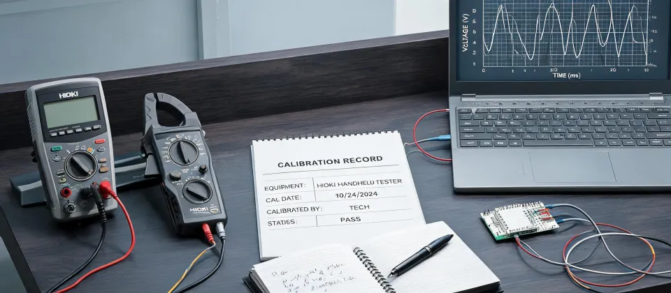
My go-to instrument in that bag is a Hioki DT4256 digital multimeter. I've owned a few Hioki multimeters over the years, and the DT4256 is the one that earns its spot. 60,000-count display, true RMS measurement, and a low-pass filter that helps when you're working near variable frequency drives. That last feature matters more than people think.
The Diagnosis That Didn't Add Up
When I got to the plant room, the contractor's technician was already testing the first sensor. He had a hardware-store multimeter—one of those $30 jobs with test leads that feel like they came out of a cereal box. He was set to DC volts, probing between the signal terminal and the panel ground rail.
"See that?" he said. The numbers were swinging between 9 and 16 volts, no pattern at all. "The transmitter's output is all over the place. Classic drift. It needs replacing."
The numbers said "replace the sensor." My gut said something else. Here's why: a 4-20 mA transmitter—which is what a differential pressure sensor of this type outputs—doesn't usually fall apart quietly on a random Tuesday. It fails hard, or it doesn't fail at all. A nine-year-old DP cell can drift, sure, but it drifts slowly and consistently. This was voltage chatter. Two completely different things.
I pulled out the Hioki. First thing I did was switch it to measure milliamps instead of volts. On a two-wire 4-20 mA loop, the current is the actual signal. Voltage across the loop depends on loop resistance, supply voltage, and whatever noise the environment throws in. I broke the loop at the controller termination, connected the DT4256 in series, and waited.
It locked onto 12.47 mA and sat there. Rock steady. If that transmitter is ranged 0 to 10 inches of water column—which it was—12.47 mA maps to about 5.3 inches of differential pressure. For that chilled water system at that time of day, with the pumps in normal operating mode, that was exactly where the process should be.
The technician stared at my display, then at his meter, then back at mine. "So why is mine jumping?"
"Because you're measuring voltage," I said. "And this loop has noise on it."
The cable shield for that run was tied down at both ends—at the transmitter housing and at the panel. In a plant room with multiple VFDs cycling, two ground points at slightly different potentials create a current path through the shield. That current couples interference straight into the signal conductors. The 4-20 mA loop itself was stable enough to ride through the noise, which is why my reading was solid. The voltage just looked terrible.
The sensor wasn't drifting. The shield was the problem.
When I compared the two measurements side by side—same sensor, same moment, two completely different conclusions—I understood again why "verify before you replace" has to be more than a slogan.
Reading the Sensus Meter to Cross-Check
Before I put anything in writing, I wanted independent confirmation that the flow was what the DP sensor said it was. The most direct way was to read the building's Sensus digital water meter on the main supply line.
I walked out to the water service entrance and lifted the meter pit cover. Here's how to read a Sensus digital water meter when you're standing in front of one:
- Wait for a full display cycle. The LCD rotates through several screens every ten to fifteen seconds. Some models start with a digit check—all 8s on the screen, which looks like a glitch but isn't.
- Catch the total consumption screen. That's the cumulative volume in gallons, the number the utility bills from. It's usually one of the first pages in the cycle.
- Watch for the flow rate page. Live usage in gallons per minute. Not every model shows this, but the one in this building did—and it was the page I needed.
- Note any status icons. Some Sensus models display diagnostic or tamper flags. If you see something unusual, check it against the utility's documentation.
I stood there through two full cycles. On the second pass, the flow rate page read 44.8 GPM.
Now, back to the numbers. If the DP sensor was reading 5.3 inches of water column across the flow element—a calibrated orifice plate on that 3-inch supply line—the flow curve says that correlates to roughly 44 to 46 GPM at the current water temperature. The Sensus meter said 44.8. The two instruments agreed within about 2 percent.
The sensor wasn't lying. It wasn't drifting. It was measuring exactly what was happening in the pipe. (Should mention: a Sensus display can sit on a blank or low-power state for a few seconds between pages. Give it a full cycle before you decide it's dead.)
The Fix That Cost One Hour
So the $1,800 quote was based on a misdiagnosis. The actual fix was floating the shield at the sensor end and keeping the termination at the panel—single-point grounding, which is what the installation drawings and the transmitter's manual had specified all along. Two ground points had created a loop that would have survived even if we'd replaced every sensor in the plant. New sensors, same noise, same "drift," same confusion three years down the road.
We taped back the shield at the sensor housing and verified the termination at the panel. The voltage readings on the tech's meter steadied immediately. All three sensors stayed in place, and none of them failed their next scheduled calibration check. (Thankfully—I'd have had some explaining to do.)
The building engineer was relieved. The contractor's technician—to his credit—took the lesson well. I don't think he was careless, for the record. He measured what he'd been taught to measure. His meter just wasn't capable of separating process noise from a real process fault. There's a real gap between a $30 multimeter and a proper instrument like the DT4256, and on a 4-20 mA signal, that gap produces expensive conclusions.
To be honest about my own decision process, there was a moment where I almost didn't push back. The contractor had an existing relationship at the property. I was the outside consultant. If I was wrong, I'd look like someone who wastes everyone's time with theory. But the cost of being wrong the other way was $1,800 and two days of manual operation. The expected value said dig deeper. The downside was an awkward conversation, which I can survive.
What I Keep Relearning
After all these years and a couple hundred inspections, I've come to believe that the most expensive phrase in facility maintenance is "just replace it." Not because replacement is never the right answer—it often is—but because replacement without verification is guessing. And you bet a real budget on that guess.
In Q1 2024, I reviewed eleven "replacement recommended" work orders for sensor failures and found that three of them were actually wiring or grounding issues. That's a 27% false-failure rate. Every one of those would have cost the facility money and not fixed the actual problem.
Here's my current checklist for any sensor complaint:
- Measure the actual 4-20 mA signal in series. If the current is stable, the sensor is doing its job.
- Check the voltage at the controller input. If it's noisy, look at the shield and the ground path before blaming the transmitter.
- Cross-check against independent data—in this case, the Sensus meter's flow rate. When two unrelated instruments agree, that's a powerful signal.
- Only then make the replacement call.
This approach worked for us because the building had a simple loop architecture and a properly maintained water meter. If you're dealing with a more complex control scheme, or a meter that hasn't been verified in years, the process will need to be different. I can only speak to what I've seen.
One more thing. The Hioki DT4256 isn't magic. It's a good tool, and it's the right one for this kind of work, but the real fix was taking a minute to verify before spending someone else's budget. I do not believe in trusting the tool over the method. It's both: method first, then the right instrument. This day, the method was "check the shield before you condemn the sensor." And the shield, as it turns out, was guilty.
Oh, and every time I see a sensor marked "failed," I add a mental note: check the shield first. That one habit has saved more money than any multimeter ever will.