It was 2:15 on a Friday afternoon when my phone rang with a number I didn’t want to see. A plant manager from an automotive parts supplier. No hello. “We’ve got three stations down. Sensors are firing randomly. Maintenance says the sensors are bad, and we’re about to order 40 replacements. Can you get here before shift change?” I glanced at the clock. The shift change was at 4:00. It was a 45-minute drive.
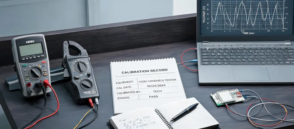
I’ve been doing emergency field support for industrial test equipment for eight years. I’ve handled 300+ rush calls in that time, and I can tell you: when someone says “the sensors are bad” before anyone has taken a single measurement, the sensor is usually not the problem. So I didn’t grab a sensor catalog. I grabbed my Hioki CM4376 clamp meter and a dedicated Hioki leakage clamp meter, and I headed out.
The $30,000 Assumption
By the time I arrived, the manager had already been talking to two sensor suppliers—one for Omron, one for Keyence. Both had sent sample units. Both were sitting on the maintenance bench. And here’s what made me nervous: both worked perfectly. Of course they did. A clean workbench isn’t a factory floor.
“We don’t care which brand is better,” he said, turning his screen toward me. It was a purchase order for 40 new sensors, almost $30,000. “We just need to pick one. Today.”
Meanwhile, a maintenance engineer pulled me aside. “Look, we’ve already tried two brands,” he said. “They work on the bench, then they start acting up on the line. If you tell me to order another batch, I’m going to lose my mind.” I said I wasn’t going to tell him that. At least not yet.
I’ve been in this position before. Actually, I’ve been in the exact position—back in 2023, we replaced 20 sensors on a packaging line and the problem didn’t go away. The client wasn’t happy, and I wasn’t proud. That experience changed how I handle these calls. The upside of a full replacement was speed. The risk was $30K and a line that still didn’t work. I kept asking myself: is the sensor really the failure point?
Why I Started with the Power Side
In my role, I don’t get paid to sell parts. I get paid to get the line running. So I started at the power side instead of the parts side. I clamped the Hioki CM4376 clamp meter around the motor lead on the nearest variable frequency drive.
Before we started, I told the manager: “Give me 20 minutes of measurements. If the data says the sensors are failing, you can still buy the replacements. But let’s know what we’re fixing.”
The waveform was ugly. Not a clean sine wave—lots of harmonic distortion and high-frequency notches. I don’t remember the exact THD percentage (don’t quote me on that), but the display was enough to tell me this wasn’t healthy. According to IEC 61000-4-30, that’s exactly the kind of measurement you need to make before drawing conclusions about equipment reliability.
Next, I switched to the leakage clamp meter and put it around the shield of the sensor cable bundle. The reading: 380 mA. On a 24 VDC control cable, that kind of current on the shield means the shield is carrying interference, not just protecting against it. I want to say the normal reading on that style of cable is under 20 mA, but don’t hold me to that exact number—the point is, 380 mA was a massive red flag.
The Caliper Clue
The most surprising clue didn’t come from a high-tech instrument. It came from a set of electronic calipers.
The maintenance tech was using them to check the mounting gap on one of the sensor brackets—making sure the sensor sat at the correct distance from its target. The readout kept jumping: 0.13 mm, then 0.21, then 0.09. I asked him to take his hand off the bracket. It still jumped. A digital caliper doesn’t do that unless it’s sitting in an electromagnetic field.
That was the moment everything clicked. The sensors weren’t faulty. The brackets weren’t loose. The sensor cables were running parallel to the VFD output cables for about four meters, and the VFD cable shields were grounded at both ends—which creates a ground loop and turns the shield into an antenna. (Should mention: this would have affected any sensor brand. Omron, Keyence, pick your favorite—none of them are designed to work in that environment.)
The Fix Wasn’t a Purchase Order
We didn’t replace the sensors. We grounded the VFD shield at one end, added a ferrite core, and rerouted the sensor cables a few inches away from the high-current cables. Maybe $60 in parts. About two hours of work.
When we powered everything back up, the leakage current on the sensor cables had dropped to around 11 mA. The current waveform on the CM4376 was clean. All three stations came back online with the original sensors in place—some Omron, some Keyence. The purchase order never went out.
Measure Before You Compare
People ask me all the time: “Omron vs Keyence, which one should we use?” Honestly, both are good products. The better question is: what’s the environment where they’ll live?
IEC 60947-5-2 sets EMC requirements for proximity sensors, but it tests them in a controlled lab. The real test is a cable tray with VFDs running next to a 24 V control line. That’s where sensors go to have problems.
So, before you compare brands—or buy 40 new sensors—spend ten minutes with a clamp meter. Check the waveform. Check the leakage current. Check the installation layout. An informed decision isn’t just cheaper; it’s the one you won’t have to make twice.